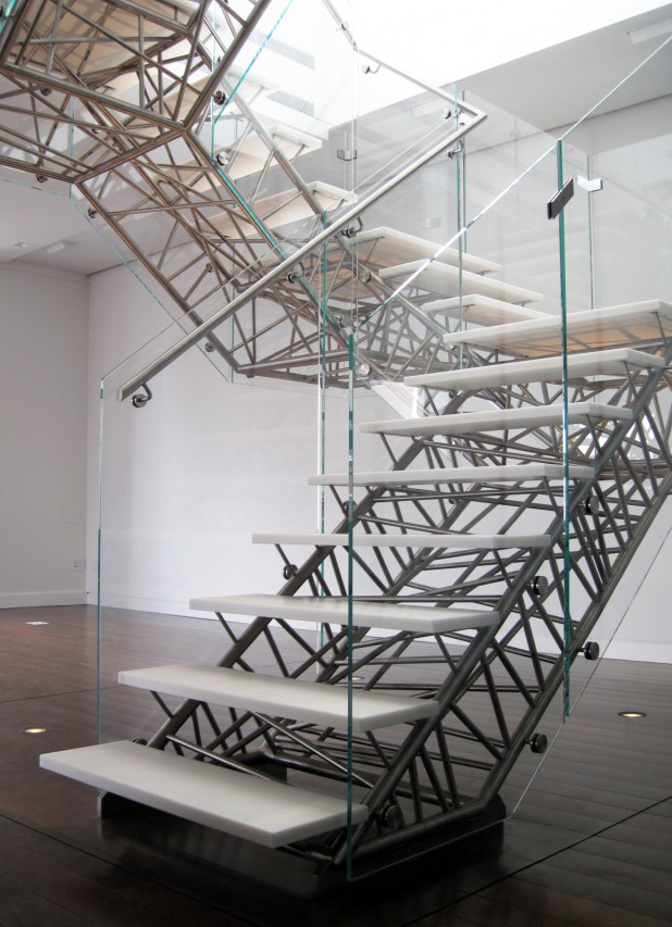
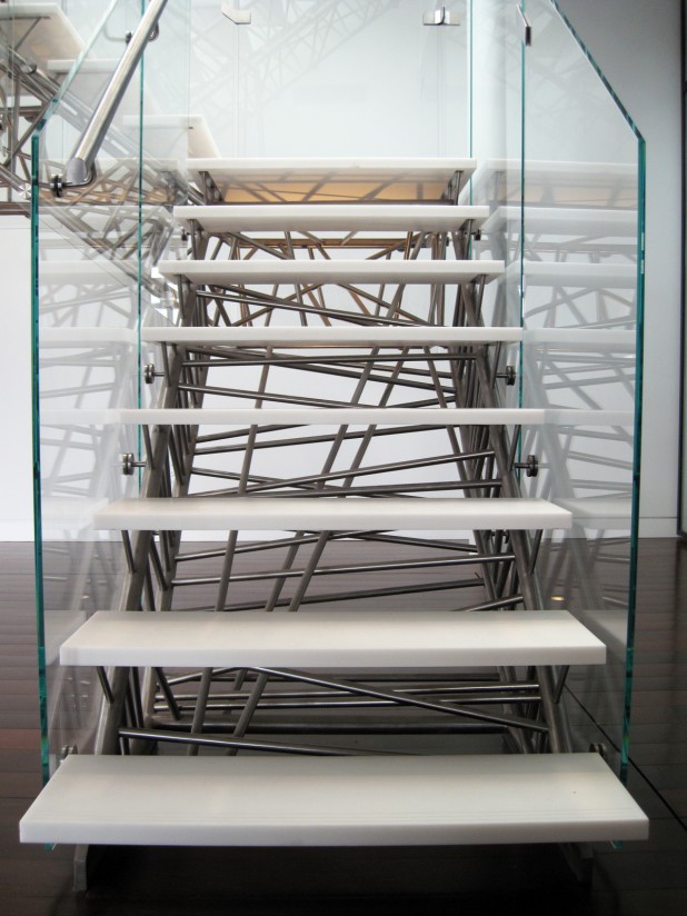
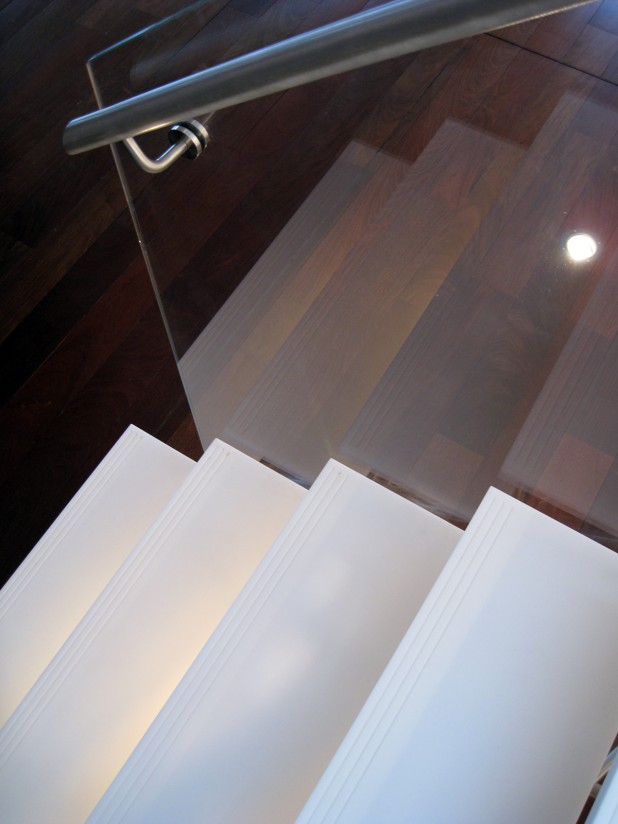
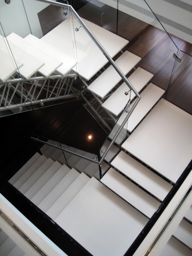
In many ways, the Genetic Stair was the most demanding project Nicholas Desbiens worked on at Caliper Studio. Though small in scale, the generative design methodology employed required a synthesis of architecture, engineering and fabrication. The project has been extensively documented, perhaps most beautifully in a set of photos by Ty Cole.
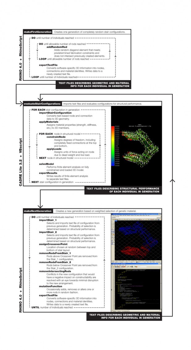
The stair is the result of an in-depth research-driven design process embodying the search for a final form that inhabits the fecund territory between exuberance and rationality. To this end custom code was developed over a period of several months to marry the generative potential of 3D architectural modeling with the analytic power of structural design software. In an entirely automated evolutionary process, populations of stairs were created in compliance with strict fabrication constraints and then rated for structural performance. Then, following genetic principles, new generations were produced in which individuals showed stronger and stronger properties until a final design was deemed structurally adequate to connect two floors with no intermediary supports while making three ninety degree turns.
The collection of videos and images below were made by Nicholas Desbiens to describe the many interrelated areas of research explored during the design, development and fabrication phases of the Genetic Stair project.
Follow this link to see Nicholas Deliver full presentation on the design and fabrication of the Genetic Stair.
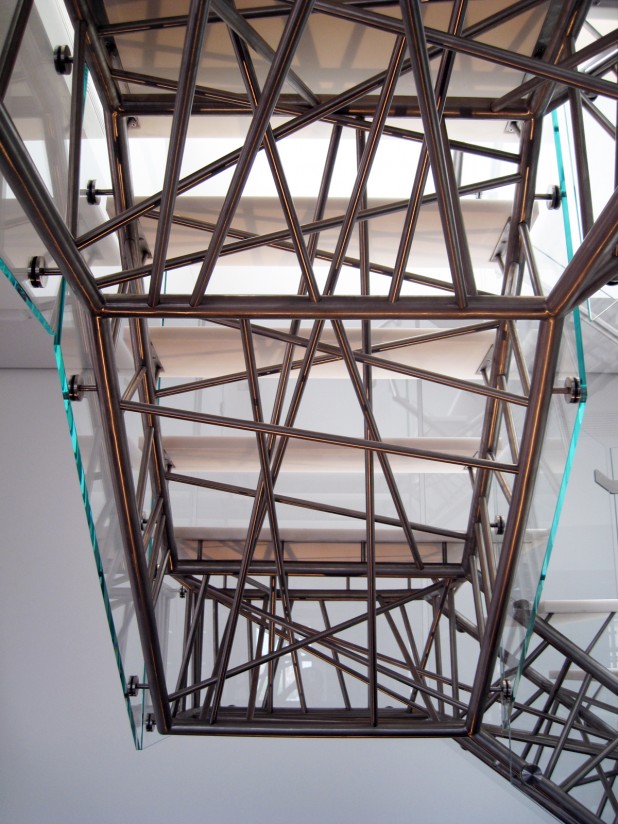
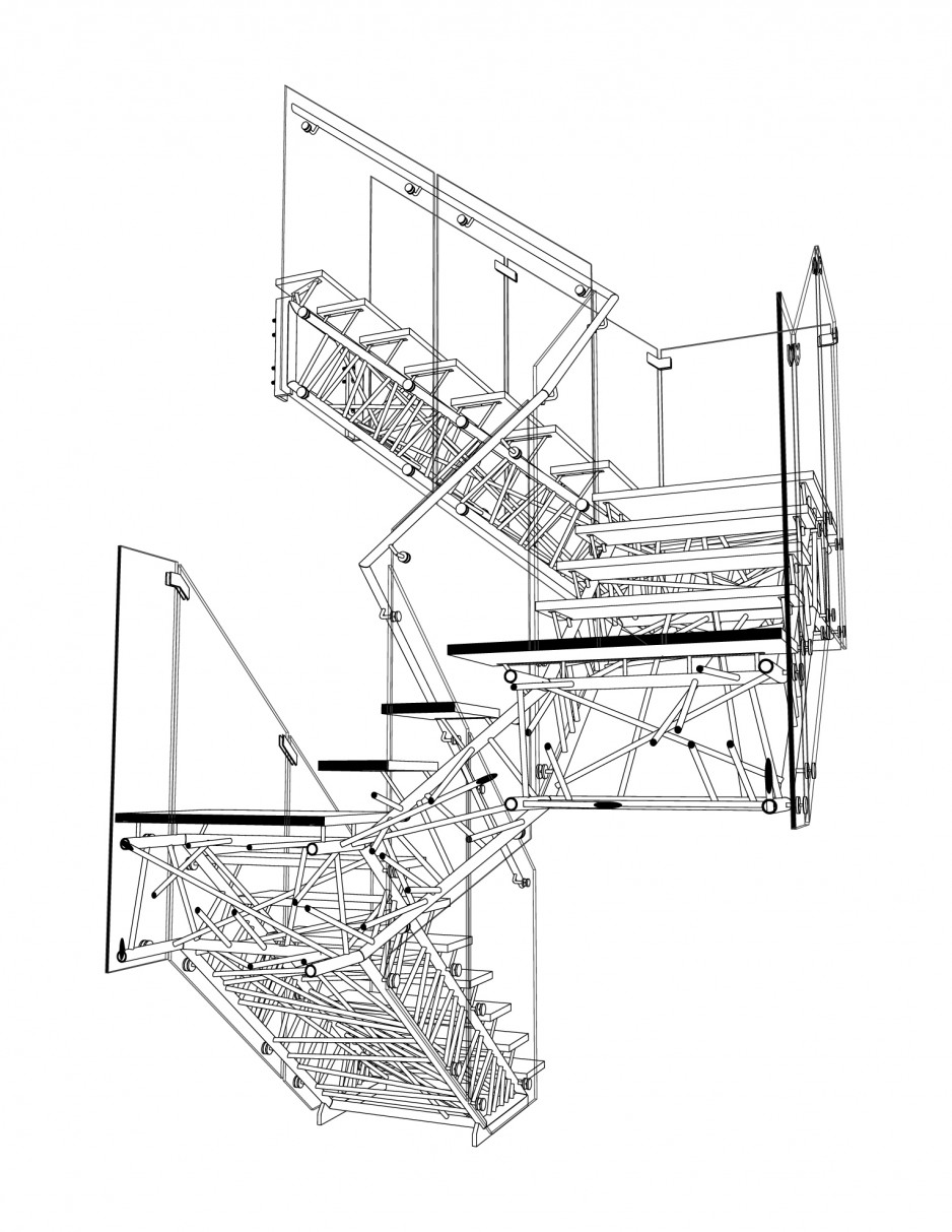
The most readily apparent result of the generative design process is a density of diagonal rods at the top and bottom, where the forces being channeled in the members are greatest.
This animation is a visualization of the techniques used to build a new stair configuration based on the geometry of previous configurations. A crossover point was chosen at random along the stair and rods below that point were taken from one stair and rods above that point were taken from another. Where conflicts arose that would jeopardize constructability, preference was given to the member taking a channeling a larger load in the previous generation.
The video to the upper right shows the portion of the generative design process recorded in this video was dubbed “The Ghost” because of its use of simulated key strokes and copy/paste techniques as a hack technique to harness the power of finite element modeling using a somewhat outdated, if affordable, software package.
What the screen shot shows is essentially the basic process of bringing geometry generated in Rhino into the FEM modeler via specially formatted text files. Then connections and loading are added prior to “solving” the model. The resulting information about vibrational frequencies, modes of deflection and loading of members is then copied out to separate text files for use in Rhino during the next generative phase.
The video below is a screen shot showing an extremely amplified visualization of the mode of vibration exhibited by the stair under live loading conditions. The frequency of this vibration was a key metric used in the iterative generative design process.
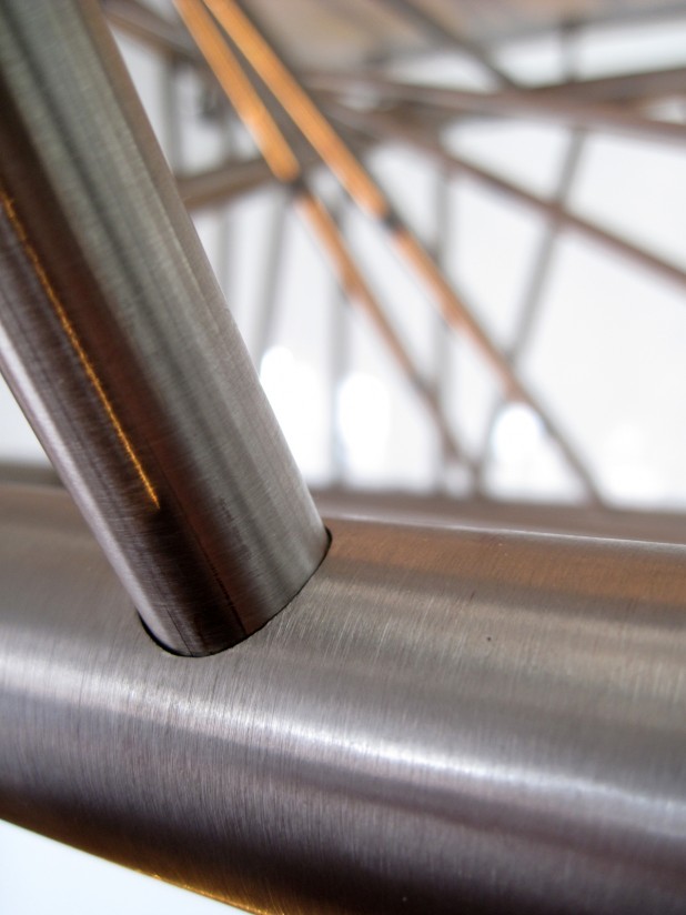
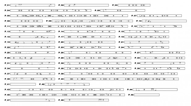
The Genetic Stair is made of 48 unique stainless steel pipes with 1400 holes and 253 connecting steel rods cut to length. Using five-axis CNC laser cutting equipment, these holes could be cut with enough precision in both position and angle to allow the pipes themselves to act as a kind of three-dimensional jig for assembling the stair. One quickly identified limitation of laser cutting technology was the relatively small range of incidence angles (< 15°) that can be precisely cut into polished stainless steel due to refraction of the beam. This constraint led to the development of highly specialized design and detailing solutions, such as fabrication-conscious generative processes and hybrid digital/analog templating procedures.
Though the laser cut pipes themselves were fabricated with a high degree of dimensional and angular accuracy, the way in which these components were joined one to the other (structural welding) was significantly less precise. To bridge the gap between the precision of digitally fabricated smart components and traditional metal shop fabrication techniques, custom jigs were made using additional digital equipment such as a CNC router, on the high end, and a standard office laser printer on the low.
Critical to the working method was a flexible design model that could be generated procedurally based on varying inputs. The video below shows the basic stair-building subroutine that locates all geometry. It was not necessary to build full 3d geometry at every iteration. Instead, a 2d/3d wireframe model was utilized and a secondary set of functions could be called to resolve the wireframe placeholders in 3d. The video to the right shows how the geometry of the stair could be pushed and pulled by changing basic input variables.
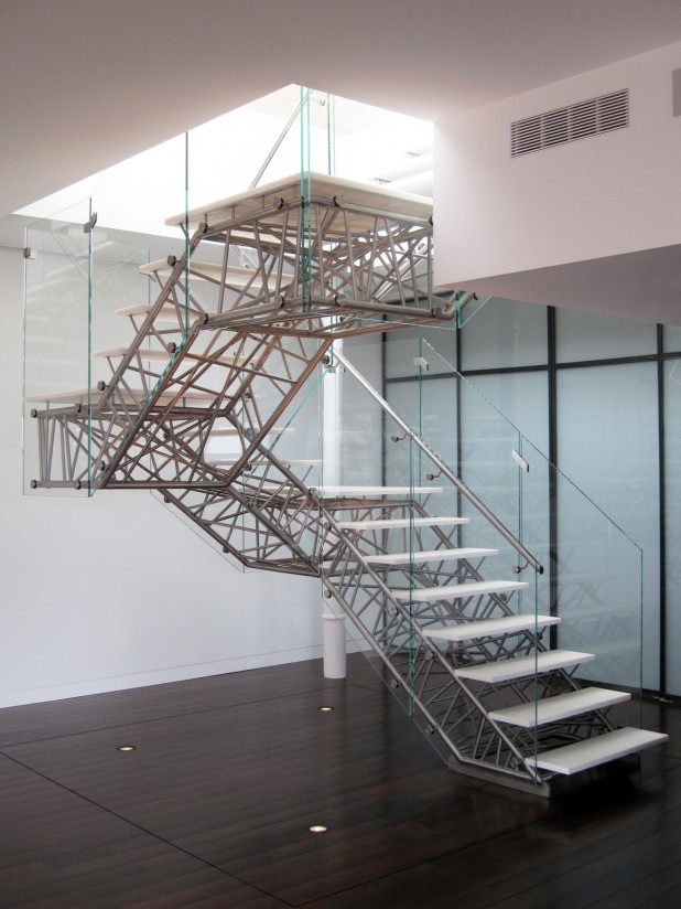
The almost minimal appearance of the stair from above was designed to reflect programmatic differences in the apartment, in which the lower floor was used for entertaining and the display of artwork, leaving the upper floor for more private use.
Although the automated computational design process was set up to avoid conflicting members, the precision of five-dimensional CNC cutting technology allowed the diagonal rods to come very near indeed, sometimes as close as one thirty-second of an inch.
Smaller diameter rod members were attached to the structural tube through a precisely-calibrated laser cut hole on the near side and a hand-finished plug weld on the far side. In addition to the 253 diagonal rods, this detail was also used to connect nineteen Corian treads, three Corian landings and eighteen planes of low-iron glass.
The final stair is a complex yet understandable architectural experience in steel and glass in which every component works together as a unified whole to push and pull the stair upward through 270 degrees with no intermediary supports.
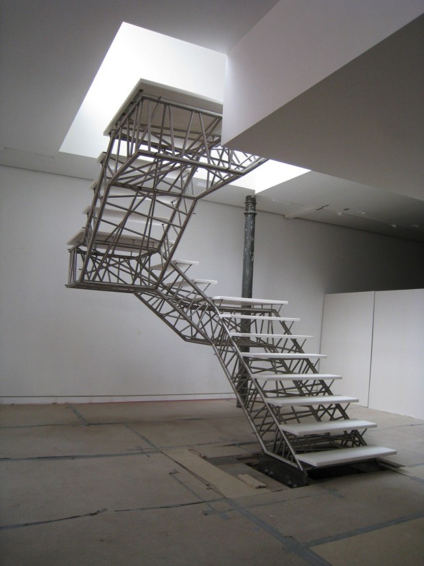
This photo was taken immediately after the installation of the main structural frame of the stair and prior to the installation of the glass handrails.
This diagram is a detailed description of the iterative computational process used to design the Genetic Stair. The design intent of the project was to arrive at configuration of simple elements that would be expressive of the complex set of forces at work in the structure. To that end, a cross-platform generative design program was developed that married the precision and adaptability of the 3D CAD environment Rhinoceros 4.0 (Rhino) with the analytic power finite element analysis (FEA) software. This program implemented a specialized genetic algorithm (GA) that integrated project-specific fabrication constraints into the generative process in Rhino while utilizing FEA to assess structural performance and assign evolutionary fitness to individual stair configurations.
48 laser cut tubes with 1400 precisely located angled holes.


